Vectors in Grasshopper
Vectors are fundamental to computational design because they define how geometry moves, scales, and orients in three-dimensional space. This tutorial provides a technical overview of vector logic and its implementation within the Grasshopper environment.
Use the Rhino and Grasshopper files "Vectors and Planes" to follow along.
Referenced Video Tutorial (Optional)
1.What is a Vector?
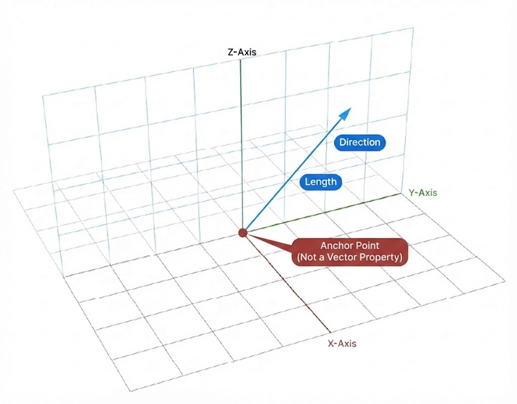
A vector represents a translation or a force. Unlike a point, which defines a specific coordinate in space, a vector is defined solely by its direction and its length (magnitude). It is important to distinguish vectors from geometry like lines or curves; while a line has a fixed start and end point, a vector is an abstract mathematical value that can be applied to any object at any location. In Grasshopper, a vector is stored as a set of three numbers {x, y, z} which describe the total displacement along each axis.
2.How to Create a Vector
There are several primary methods for generating vectors depending on whether you are working with coordinate data or existing geometry.
Vector XYZ
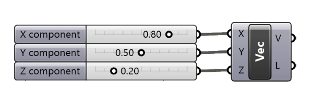
The most direct way to construct a vector is using the Vector XYZ component. By providing numeric values for the X, Y, and Z parameters, you define the displacement from the world origin {0,0,0}. This is useful for creating specific translations or defining forces based on calculated numeric data.
Unit Axis Vectors and Length
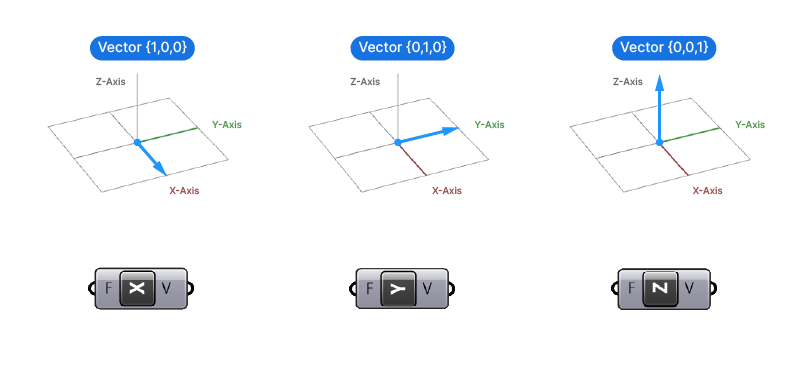
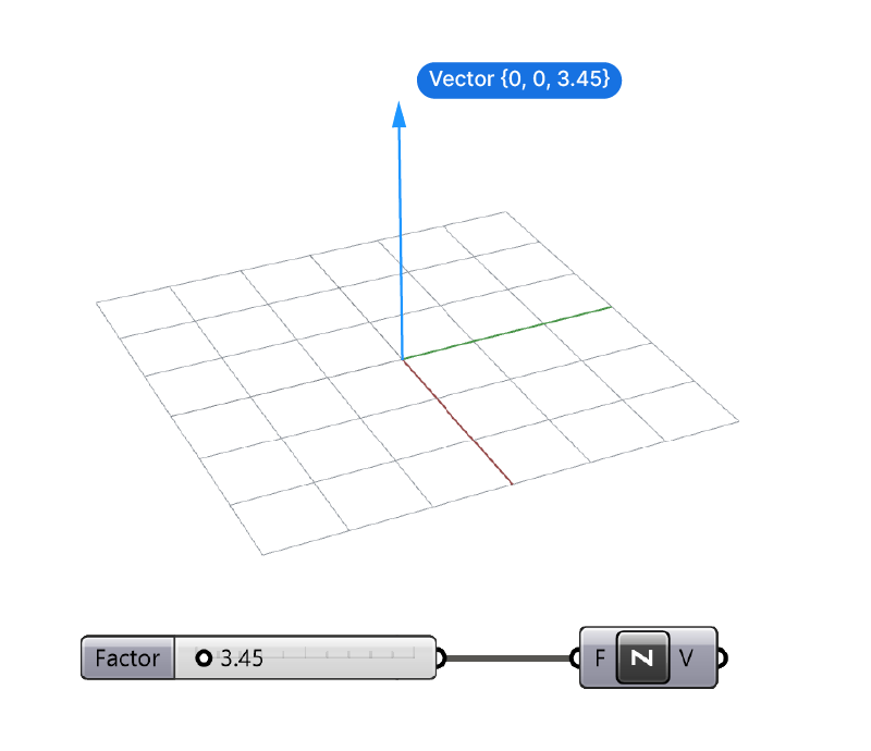
Grasshopper provides dedicated components for the world axes: Unit X, Unit Y, and Unit Z. These components produce a unit vector (length of 1) by default. To set a specific length, you must connect a numeric value to the Factor (F) input. This effectively creates a vector that is both aligned with a global axis and scaled to a precise magnitude.
Vector 2Pt
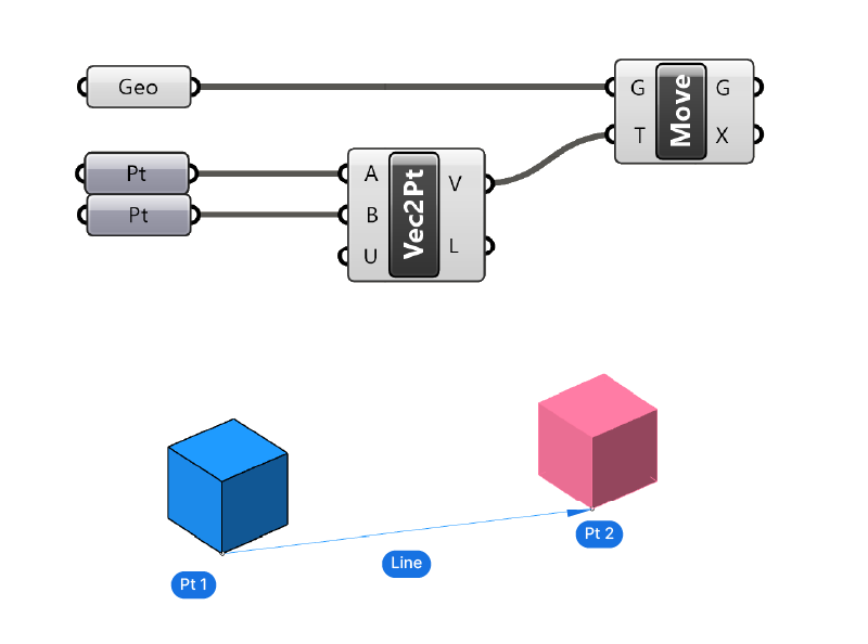
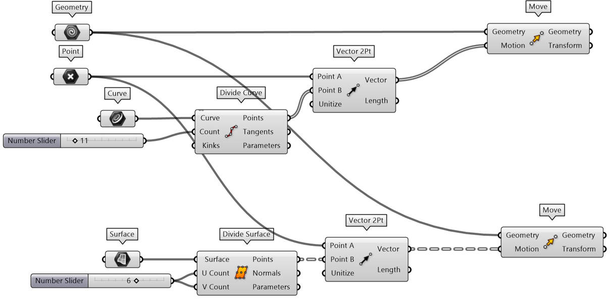
The Vector 2Pt component creates a vector between two specific points. This is used when you need geometry to move from one location to another. The resulting vector represents the exact distance and direction required to translate an object from point A to point B.
Line Geometry as Vector
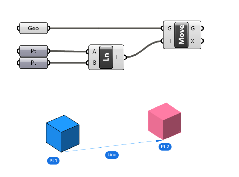
In Grasshopper, Line geometry is often interchangeable with vector data. If you connect a Line parameter directly into a Vector input, Grasshopper automatically extracts the vector representing the direction and length of that line. This behavior is functionally identical to using the Vector 2Pt component with the line's start and end points.
3.How to Visualize a Vector
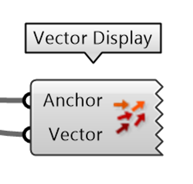
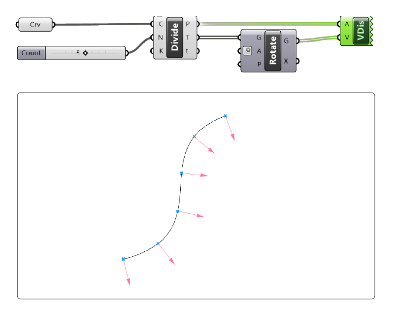
Because vectors are mathematical data and not physical geometry, they are invisible in the Rhino viewport. To see them, you must use the Vector Display component. This component requires two inputs: the vector itself and an anchor point. Since a vector has no fixed location, the anchor point tells Grasshopper where to draw the arrow in the viewport. This is strictly a preview; the arrow cannot be baked into Rhino as a line unless converted using the Line SDL component.
Line SDL (Length and Direction)
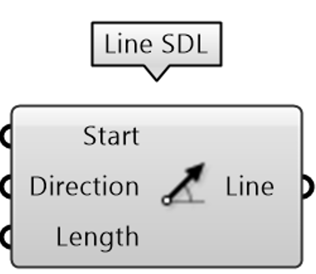
Vectors are used to establish geometric relationships that are not tied to the world grid. The Line SDL component creates a line starting from a point (S), following a Direction vector (D), for a specific Length (L). Even if a numeric length value is provided, the orientation must be established through a vector input.
4.Vector Operations
Manipulating vectors allows for complex spatial logic. Three primary operations are essential for most workflows.
Addition
Adding two vectors results in a single vector that represents the combined movement of both. Geometrically, this is equivalent to placing the second vector at the tip of the first. This operation is useful when combining multiple forces or movements into a single transformation.
Multiplication
Multiplying a vector by a scalar value changes its length while maintaining its direction. This operation is used to scale movements or forces proportionally. For example, multiplying a unit vector by 5 creates a vector five times longer in the same direction.
Reverse
Reversing a vector inverts its direction while keeping its magnitude the same. This is equivalent to multiplying the vector by -1. Reversed vectors are useful for creating symmetrical operations or when you need to move geometry in the opposite direction of an existing vector.
Unitizing
Unitizing takes an existing vector of any length and scales it so that its magnitude becomes 1.0 while maintaining its original direction. This is a critical step before using vectors for orientation or as inputs for components that expect pure direction.
Amplitude
The Amplitude component is used to change the length of a vector to a specific value without changing its direction. It functions by first unitizing the input vector and then multiplying it by the desired magnitude. This is the most efficient way to control the distance of a translation.
Rotate Vector
Rotating a vector changes its direction while maintaining its magnitude. This is done by applying a rotation transformation around a specified axis by a given angle. It's useful for reorienting geometry or creating rotational patterns without changing the distance of movement.
5.Extracting Vectors from Curves and Surfaces
Data-driven design often requires extracting directional information from existing shapes.
Tangents from Curves
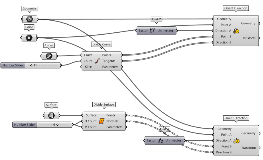
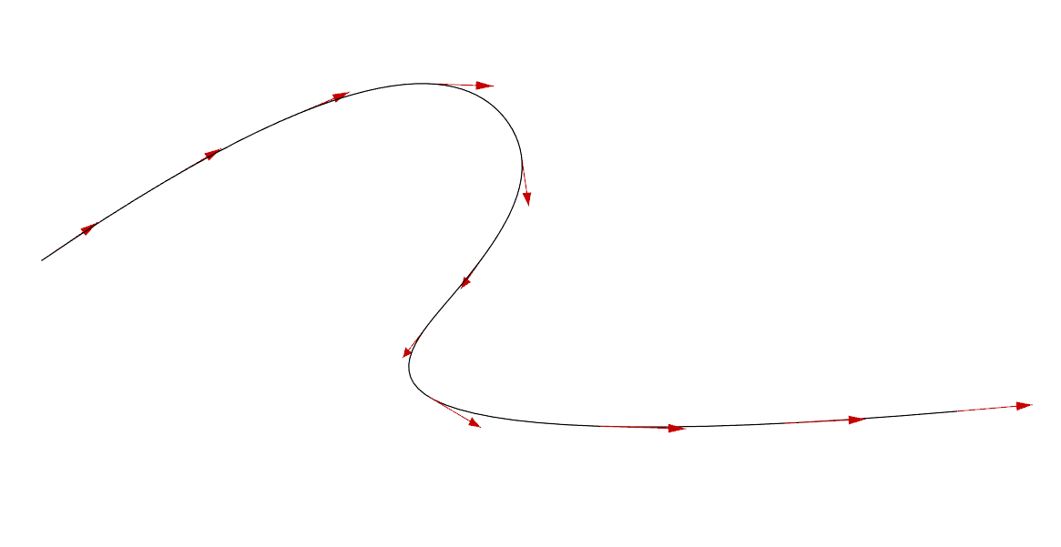
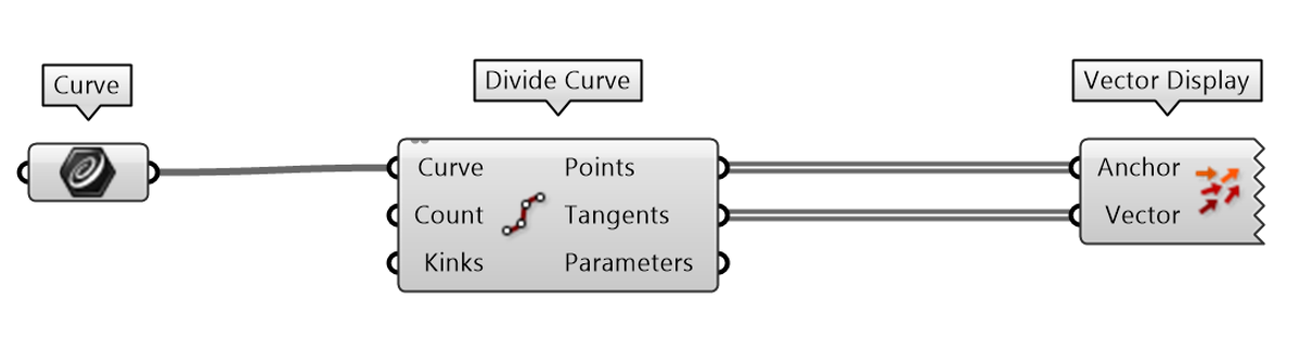
When using the Divide Curve component, the Tangents (T) output provides a vector at every division point. These vectors indicate the direction the curve is heading at that specific location. Tangents are used to align objects along a path or to orient geometry to follow a specific flow.
Normals from Surfaces
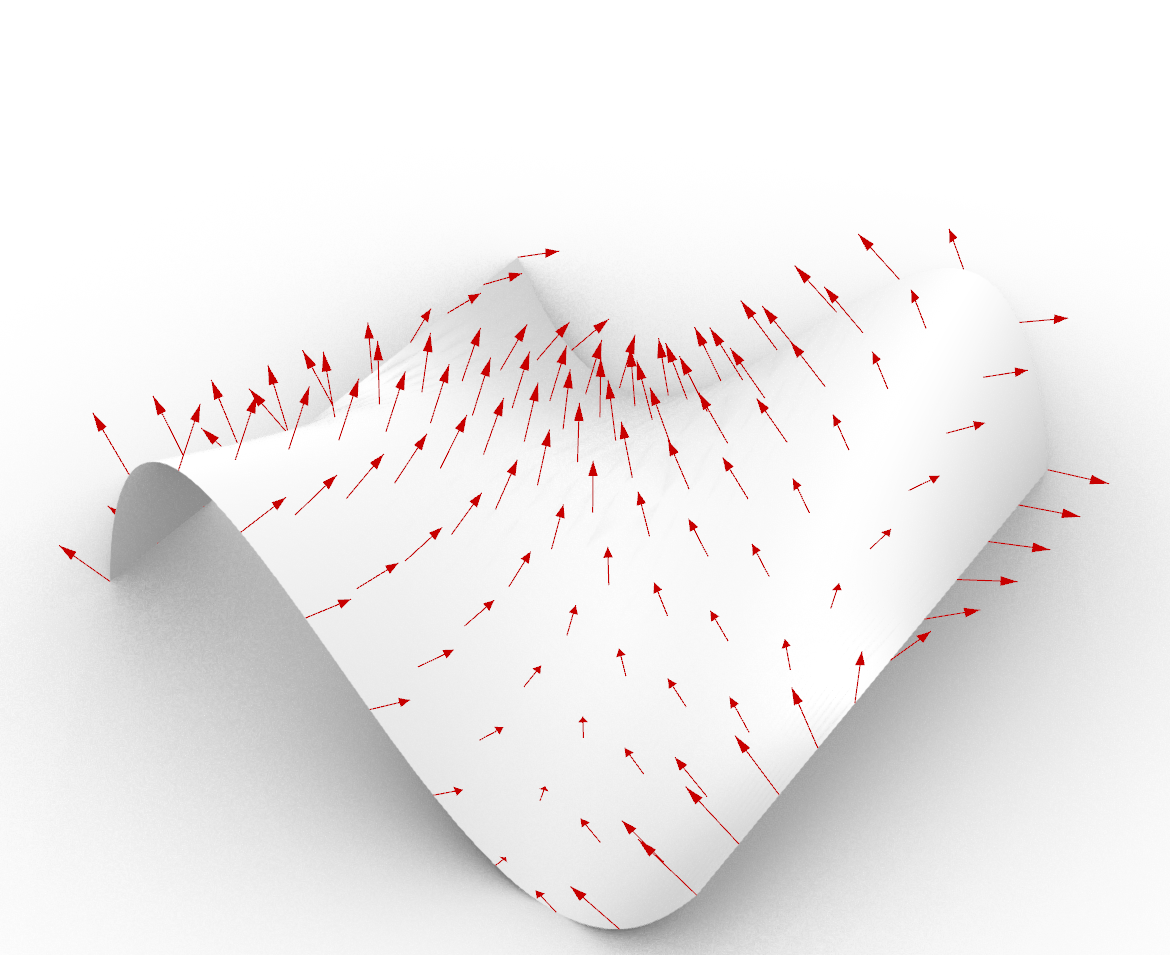
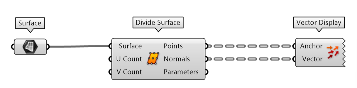
The Divide Surface component provides a Normals (N) output. A normal is a vector that is perpendicular to the surface at a given point. This is essential for extruding panels, offsetting geometry, or orienting components so they sit flat against a curved face.
Evaluation Components
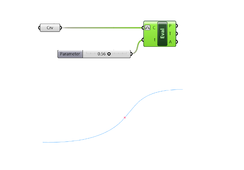
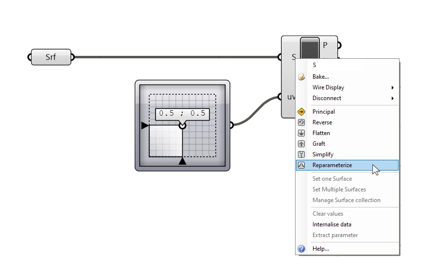
For more precise control, you can use the Evaluate Curve or Evaluate Surface components. These allow you to retrieve tangent or normal vectors at specific local coordinates (parameters) without the need to subdivide the entire geometry. These components are preferred when you need a vector at a single, specific location on a complex shape. Make sure to reparametrize the curve/surface input, by right-clicking on the input and toggling ‘Reparametrize’.
6.What to use Vectors for
Vectors are the primary drivers for geometric transformation components. They act as the instruction for how far and in what direction a change should occur. While there are countless applications in parametric modeling, the examples below illustrate the most common use cases.
Extrude
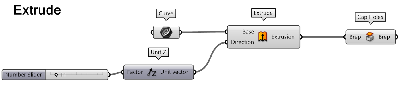
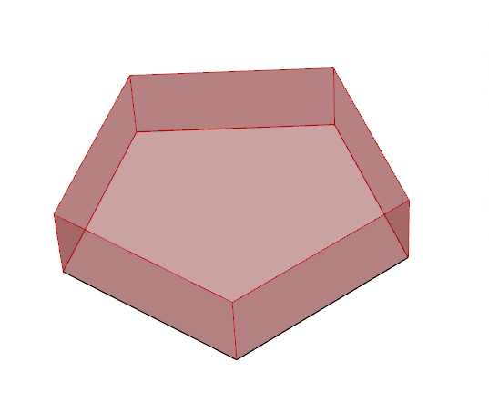
Extrusion turns 2D profiles into 3D forms. The Extrude component requires a Direction vector (D). The length of this vector determines the height or depth of the extrusion, while the direction defines the axis of growth. For architectural massing models, this is often a Unit Z vector multiplied by a floor height value.
Move
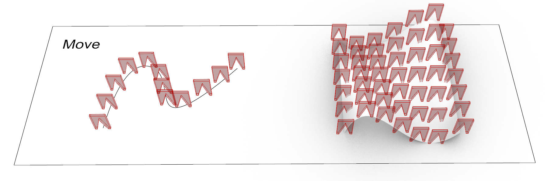
The Move component requires a Translation vector (T). In this context, the vector defines the exact offset from the object's current position. If you plug a Unit X vector into the Move component, the object will move exactly one unit in the positive X direction.
Orient Direction
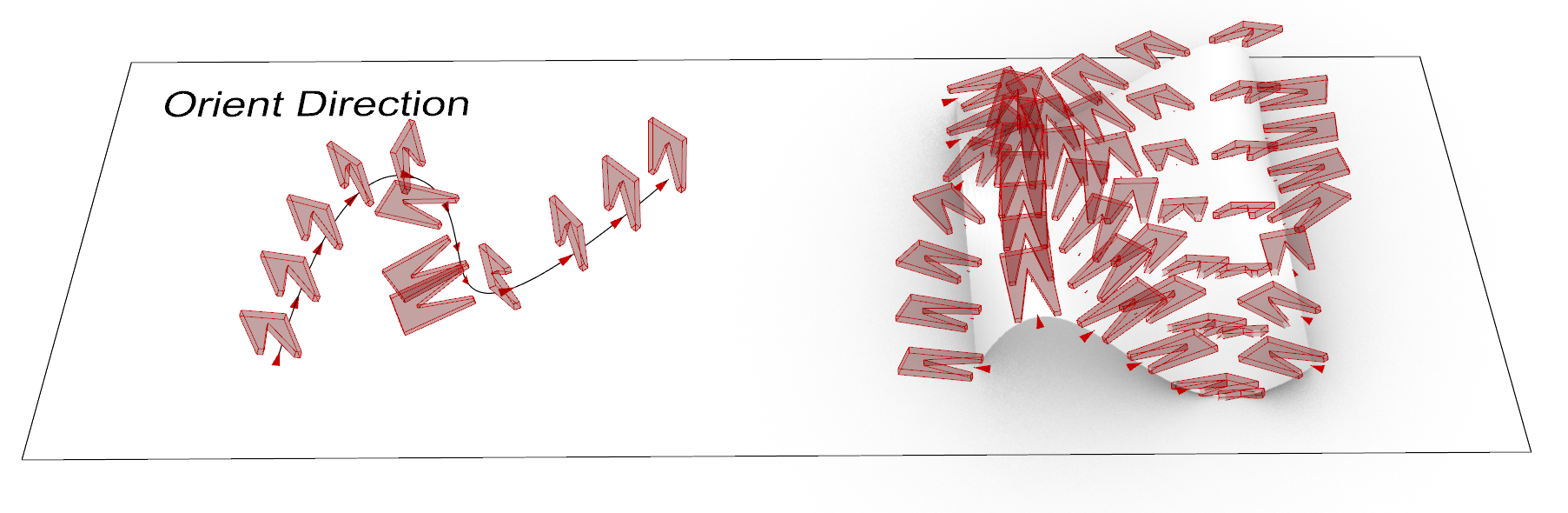
The Orient Direction component allows you to re-align geometry by specifying initial and final direction vectors. This is particularly useful for orienting objects relative to surface normals or curve tangents. By matching a local vector of an object to a target vector in the scene, you can ensure precise alignment without manually constructing full reference planes.