Tutorial 2.3: Robotic Fabrication
This tutorial introduces robotic fabrication through the Robots plugin for Grasshopper. You will learn to program a UR30 robot arm digitally — designing toolpaths, simulating motion, and understanding the pipeline from geometry to robot code.
DDS Fabrication Submission Process
If you want to use the CNC or other digital fabrication equipment in the DDS lab in the future, please refer to the document shared by the fabrication team for details on who to contact, what the submission process looks like, and how to book time.
Part 1: Programming the UR30 with Grasshopper
The robot we have in the DDS lab is a Universal Robots UR30 — a 6-axis collaborative robot arm with a 1300mm reach and 30kg payload. It has 6 rotational joints giving 6 degrees of freedom, meaning it can reach any position + orientation within its reach sphere (if no singularity occurs).
Files:
- UR30_Workspace.3dm— Rhino file with the DDS workspace layout, example tool geometries, and test curves. Open this file and follow the video tutorial.
- UR30_simple toolpath.gh — Grasshopper file for reference only. I strongly recommend you follow the video tutorial and build the components yourself — that's the most efficient way to learn. This file is there to check your work afterwards. It also contains a few additional components not covered in the video (specifically for sending programs to the real robot for safety reasons).
Video Tutorial:
Watch the video walkthrough. The video covers the full workflow step by step.
Below is a summary of the key components and steps covered:
Install the Plugin
- In Rhino:
_PackageManager→ search Robots → Install → Restart - Plugin page: food4rhino.com/en/app/robots
- GitHub & docs: github.com/visose/Robots
Load the Robot
Load Robot System→ Libraries button → install Universal Robots → select UR30
Core Pipeline (4 components you always need):
Load Robot System— loads the UR30Create Target— defines positions as planes (position + orientation). The robot needs both where to go AND which direction to face — that's why we use planes, not points.Create Program— compiles targets into a robot program. Generates URScript, the native language of Universal Robots.Program Simulation— previews the motion in Rhino (use a Number Slider on Time input)
Target settings (right-click Create Target to add inputs):
- Motion — Linear (straight line, for fabrication) vs. Joint (curved arc, for repositioning). Joint moves all axes simultaneously and avoids singularities. Linear is precise but can trigger singularities.
- Tool —
Create Toolwith TCP (Tool Center Point = offset from flange to tool tip), mesh visualization, and weight - Configuration — shoulder/elbow/wrist toggles to change the robot's pose. The robot can reach the same point in multiple poses.
Tool setup:
- Turn on the tool_01 layer in the workspace file
- Reference the tip point →
YZ Plane→ TCP input - Reference the tool mesh → Mesh input on Create Tool
Curve-based toolpath:
Divide Curve→XY Plane+Flip Plane→ Create Target (tool points down, fixed orientation)Perp Frame→ Create Target (tool follows curve direction)Horizontal Frame→ Create Target (follows curve, stays level)
Visualization:
Simple Trail(Robots → Utility) — shows the motion path between targets- Right-click any Number Slider → Animate to auto-step and export frames. Compose a video from the frames or just do a screen recording while Animate.
Exporting to real robot (for reference):
Save Program— exports URScript to a file (transfer via USB)Remote Connection— streams program via ethernet cable + IP address
Debugging (when Create Program turns red):
- Move the toolpath closer to the robot or change its orientation
- Toggle Configuration settings (shoulder, elbow, wrist)
- Split complex toolpaths into smaller segments
Part 2: Pick-and-Place Script Reference (Optional)
This is the Grasshopper script for the pick-and-place exercise we demonstrated in the DDS lab. This script is quite complex — the goal is not to dive deep into every step, but to look through the overall structure and understand the framework for any robotic fabrication project.
The major parts of the script follow this process:
- Select the robot — Load Robot System, define the workspace
- Define the tool — Create Tool with TCP, mesh, and weight
- Design the toolpath — this is the main design work; figuring out the orientations of the planes, how to design the TCP approach path, and how the end effector interacts with the geometry
- Create targets — Convert the designed planes into robot targets with speed, zone, and motion settings
- Generate URScript — Create Program compiles everything into robot-native code
- Simulate — Program Simulation to preview and verify before sending to the real robot
This framework is the same whether you're doing pick-and-place, drawing, milling, or any other robotic process. The creative design work is usually in step 3 — designing the toolpath and the tool orientation.
Exercise 2.3: Robotic Milling Simulation
Due: Friday, March 13 at 11:59 PM on Canvas
Format: Screen recording (MP4/MOV)
Points: 3
In Lecture 2.3 we looked at the Digital Stone project — a robotic milling example. Your task: reproduce a digital simulation of this milling process using the UR30.
🔗 Reference video: YouTube link
What to do:
- In the same UR30 workspace.3dm file, turn on the layer called Simple Stone Geometry/Surface. This contains a simplified stone surface inspired by the project.
- You only need to create a toolpath for one side of the geometry (the simple stone surface). You don't need to do both sides.
- Modify from the script you developed in part 1, build a Grasshopper definition that loads the UR30, generates a toolpath along this surface, sets up a tool with TCP, and simulates the milling motion.
- Record a screen recording of the simulation.
Example Video:
Hints:
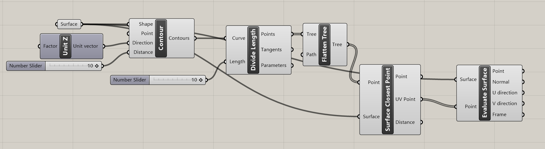
You are free to design the toolpath on the stone however you like. One possible workflow:
- Use the
Contourcomponent to create horizontal section curves across the surface - Use
Divide CurveorDivide Lengthto get points along those contour curves - Use
Surface Closest Pointto find the closest UV parameter on the surface for each point - Feed those UV Point outputs into
Evaluate Surfaceto get oriented surface frames at each point - You need to
Flattenthe data tree - These frames are ready to feed into
Create Target
(Screenshot of this workflow attached below)
External Resources (not needed for the exercise)
🔗 Robots Plugin — Official Docs: github.com/visose/Robots/wiki
Note: example files may not work directly with our UR30 lab setup, but useful for understanding the plugin.
🔗 All GH Robotics Plugins Compared: github.com/robin-gdwl/Robots-in-Grasshopper
Additional resources — not all UR-specific, but helpful for robotic fabrication workflows:
🔗 MSD Robotics Lab (Uni Melbourne): ms-kb.msd.unimelb.edu.au/.../create-a-basic-robot-program
🔗 QUT Design Robotics: designrobotics.net/.../robot-fabrication-using-rhino-and-grasshopper
🔗 Fab Lab BCN Wiki: wiki.fablabbcn.org/ROBOTS
🔗 Pratt Pi-FAB: pi-fab.com/robotics
🔗 UNSW Making: making.unsw.edu.au/.../grasshopper-script-for-universal-robots