Planes in Grasshopper
Planes are fundamental to parametric modeling because they define local coordinate systems. While a point defines a location and a vector defines a direction, a plane provides a full frame of reference: an origin combined with X, Y, and Z axes. This tutorial outlines the construction and application of planes as the basis for geometric orientation.
Use the same Rhino and Grasshopper files "Vectors and Planes" to follow along.
Referenced video tutorial (Optional)
1. What is a Plane?
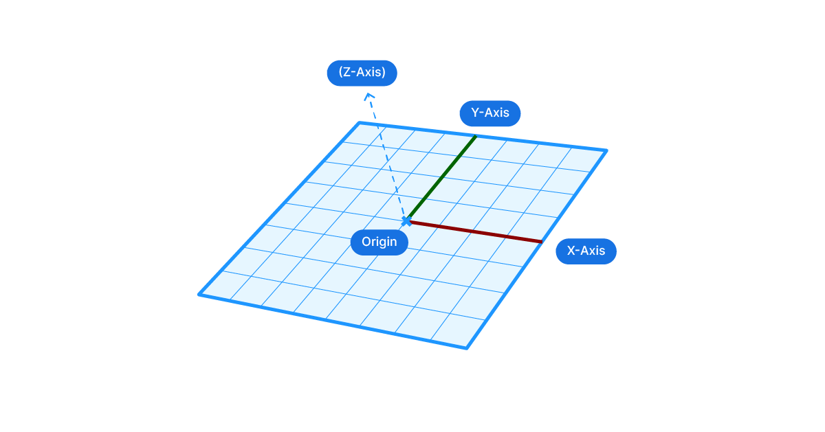
A plane is a mathematical construct representing a flat, infinite surface. It is defined by an origin point and two vectors that establish its local X and Y axes. The Z-axis is always perpendicular to both X and Y. In Grasshopper, a plane is described as {P, X, Y}, where P is the origin point.
The Right-Hand Rule
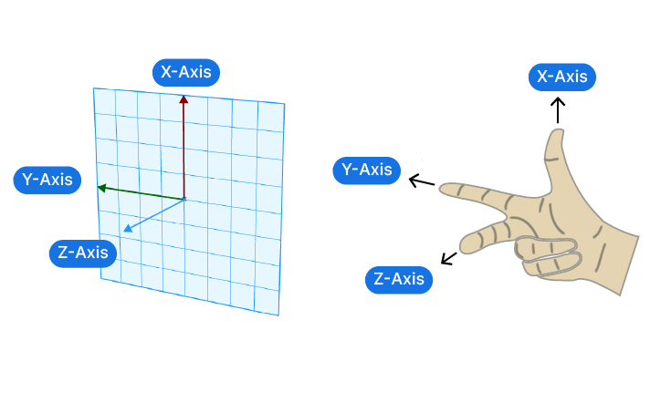
The orientation of a plane follows the Right-Hand Rule. This rule determines the direction of the local Z-axis (the normal).
If you point your right thumb in the direction of the local X-axis and your index finger in the direction of the local Y-axis, your middle finger (pointing inward toward your palm) indicates the positive Z-axis. Understanding this is essential because flipping the order of points or vectors when creating a plane will invert the Z-axis, causing geometry like extrusions or offsets to move in the opposite direction.
2. World Planes
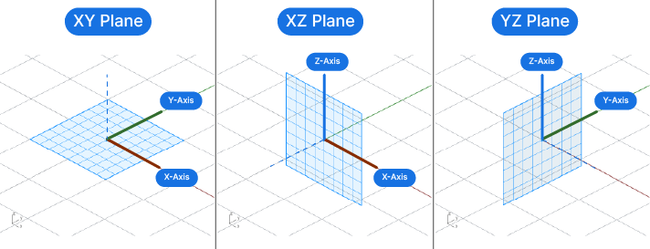
Grasshopper provides three default components that correspond to the global coordinate system:
- XY Plane: The horizontal "ground" plane (Z=0).
- XZ Plane: The vertical "front" plane (Y=0).
- YZ Plane: The vertical "side" plane (X=0).
These are the most common starting points for creating grids, circles, or polygons.
3. How to Create a Plane
Beyond the world defaults, you can construct custom planes to align with specific design intentions.
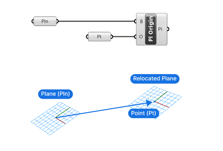
Plane (Origin)
The simplest way to create a plane is to provide a new origin point. By default, this component creates an XY plane centered at that point. This is the standard method for translating the global coordinate system to a new location without changing its orientation.
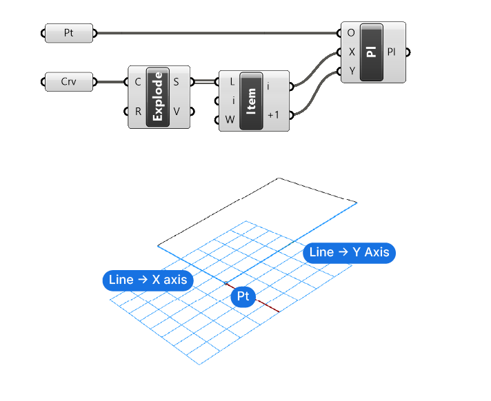
Construct Plane
This is the most comprehensive method for building a plane from scratch. It requires an origin point, a vector for the X-axis, and a vector for the Y-axis. Grasshopper will automatically ensure the axes are perpendicular to each other to maintain a valid coordinate system.
Plane 3Pt
This component defines a plane based on three points:
- Origin (O): The center of the plane.
- Point A: Establishes the direction of the local X axis.
- Point B: Defines the plane's orientation in space, which determines the Y axis. This is essential for creating skewed or angled coordinate systems based on existing geometric vertices.
Plane Normal
The Plane Normal component requires an origin point and a Z axis vector. It is the most common way to make a plane "look" at something or follow a specific direction. For example, using a surface normal as the input vector will align the plane perfectly flat against that surface.
4. Extracting Planes/Frames from Geometry (Analogy to Vectors)
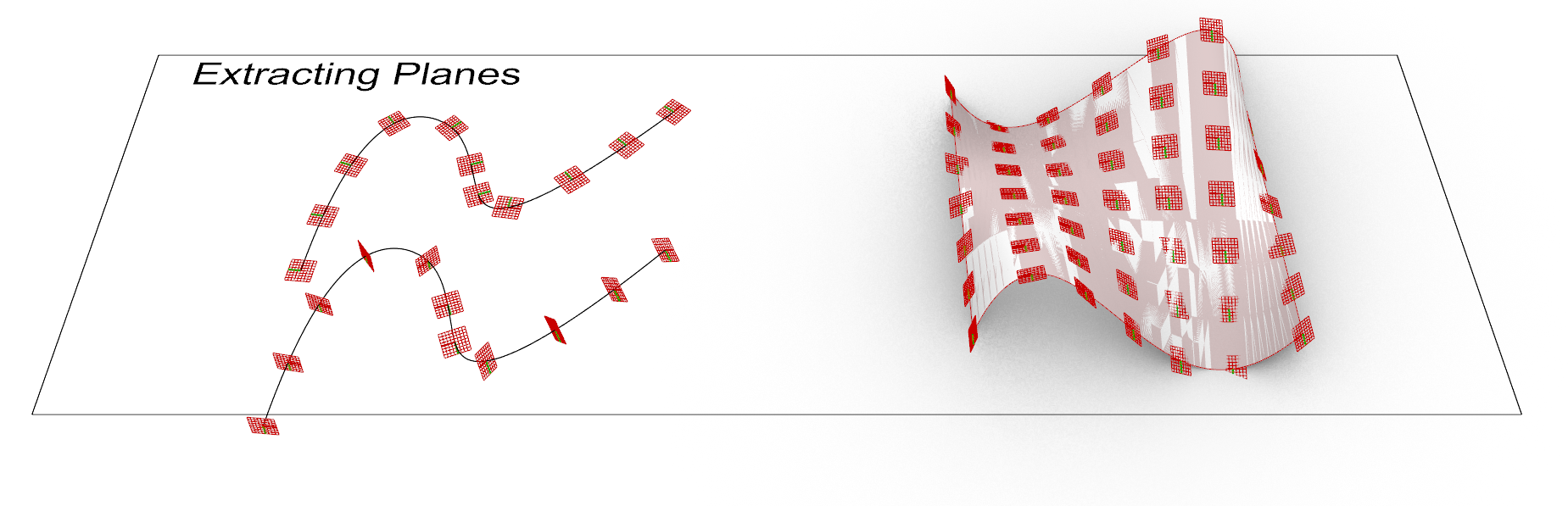
While basic division components extract tangents or normals as vectors, more advanced evaluation components extract full coordinate systems, often called "Frames", as planes.
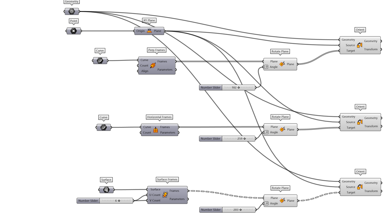
Perp Frames (Curve)
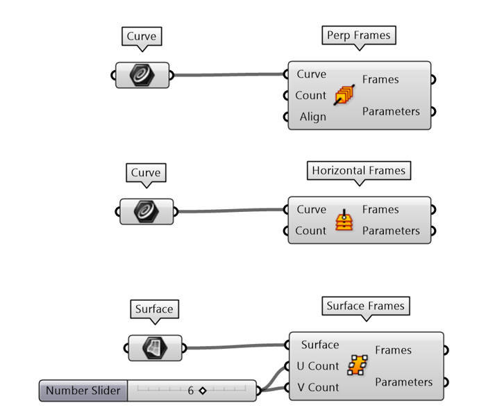
The Perpendicular Frames (Perp Frames) component is analogous to the "Tangent" output of a Divide Curve component. While a tangent only gives you a direction, a Perp Frame gives you a full plane that is perpendicular to the curve at a specific point. This is the mandatory starting point for Sweep operations or creating cross-sections along a path.
Note: There are other components designed to retrieve frames from curves depending on the desired orientation. For instance, Horizontal Frames (HFrames) ensures the local X-axis remains parallel to the XY plane, which is vital for architectural elements like stair treads or railings. Additionally, Evaluate Curve can provide a frame at a specific curve parameter.
Surface Frames
When working with surfaces, the Divide Surface component primarily returns points and normal vectors. To obtain full coordinate systems, use the Surface Frames component, which generates planes across the surface grid. These frames align their local X and Y axes with the U and V iso-curves of the surface, while the Z axis remains consistent with the surface normal. This establishes a precise mapping for the orientation of components relative to the local curvature and flow of the surface.
Note: Similar to Evaluate Curve, the Evaluate Surface component provides a frame at a specific U,V coordinate.
5. What to use Planes for?
Planes are the required input for any component that needs more than just a location. Geometry like Circle, Rectangle, and Box all require a plane to determine their orientation in space. Without a custom plane, these components default to the World XY plane.
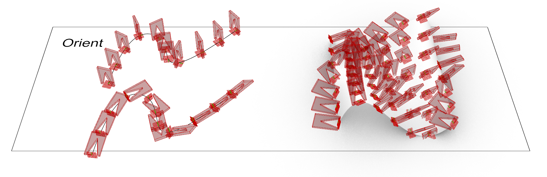
Orient
The Orient component is perhaps the most powerful application of planes. It re-maps geometry from a Source plane to a Target plane. By using extracted frames (like those from Perp Frames or Surface Frames) as target planes, you can accurately place complex geometry along curves or across surfaces, ensuring that the local orientation of the object matches the local coordinate system of the host geometry.